/robowaifu/ - DIY Robot Wives

Advancing robotics to a point where anime catgrill meidos in tiny miniskirts are a reality.

Build Back Better

More updates on the way. -r

Max message length: 6144

Drag files to upload or
click here to select them

Maximum 5 files / Maximum size: 20.00 MB

More

(used to delete files and postings)


Have a nice day, Anon!


Actuators for waifu movement! Robowaifu Technician 09/18/2019 (Wed) 11:27:47 No.406
Hello fellow Anons! Kiwi here to provide basic educational facts about various actuators we can use for gifting artificial avatars of our hearts desire motion!

1. Let's start with a personal favorite, the impractical, inefficient yet oh so fascinating: Heated Twisted Nylon!

What are they? They're nylon threads which have been spun around then annealed to seal in their coils. A heating method causes these threads to then contract or expand.

Good: Why is this a personal favorite? Simply put, it's natures muscle substitute for muscles. To elaborate, this marvelous invention contracts like human muscles, has a similar practical strength/weight/volume as human muscle. Icing on this proverbial cake comes in its incredibly low cost of manufacture. Materials needed are nylon threads and a heating element. A fixture for production can be produced simply, operated with incredible ease, all while having a low cost. It very well could have revolutionized all of robotics if it weren't for its flaws.

Bad: This is honestly a terrible actuator. Its greatest flaw comes from its speed. they aren't as fast as human muscles unless they're underwater. Water reduces efficiency to unacceptable levels if they're powered by batteries. Water is also rather heavy. If used, you'd have a waifu that moved slowly , would seize up in hot weather, and her battery would die rather quickly. Final nail in the coffin: it's very difficult to get positional control.

2: Pneumatics, moving her booty with air!
What is it? Pressurized air is guided to an actuator where its energy turns into motion. Popular air actuators include rotary turbines, cylinders, and air muscles.

Good: Actuators are light for their power. Positional control isn't difficult to attain. They can be faster then human muscles. Heating elements can be used to augment performance to higher levels.

Bad: These things require electrical actuators to function properly. Thus, they're inherently more complex then electrical counterparts. They need a source of compressed air, either from a tank or a compressor and a tank. Compressors are large, heavy, noisy, all around unsuitable to be incorporated into a waifu. Air tanks would also run out rapidly unless she's barely moving. Overall, they're suited better for industrial use.

3. Hydraulics, they're like pneumatics except stronger, needs a return system, needs an onboard pump, gets hotter, generally costs more, and is heavier.
(2 and 3 are great for stationary machinery which requires high power as they're very cost effective as high power actuators)

4. AC motors
What are they? They're rotary devices which use AC current to create magnetic flux used to provide torque.

Good: Generally highly efficient with good thermal characteristics. Can have controllable speed and torque.

Bad: They run off of AC electricity, batteries don't provide that. It's not difficult to change DC to AC but, it's a layer of extra cost and complexity. Overall they're great but the next actuator is better suited for our purpose.

5: DC motors are the ideal actuator for smaller waifus.
What are they? They're actuators which convert DC electricity into rotary mechanical energy.

Good: They're inexpensive, easily attainable, and simple to control. They're very easy to control. Uses DC which batteries provide.

Bad: Need to be geared down to provide good torque. They're middle of the road efficiency wise.

(For smaller waifus, their lower efficiency compared to the next actuator isn't a major concern. Smaller batteries recharge rapidly, so having her need to charge in her bed isn't a big deal.)

6. Superior Brushless Motors are ideal actuators
What are they? DC motors which need specialty hardware to drive them.

Good: High efficiency, it's the most efficient option available.

Bad: Controllers add expense and complexity.

(1 of 2)
>>12389 I'm currently toying around with a linear actuator system that uses 10 dime-thin actuators circling in a ring around the torso volume, and connecting the pelvic section & the chest section ala Anon's OSMR design. (>>12165) Each actuator will be roughly 1 foot in length for the outer casing. I'm hoping for approximately 6 inches of throw (or better) internally on the actuator rods. Can you think of an actuator design that works on the principles you are promoting, rather than the more mundane (and slower/noisier) screw-type design?
>>12390 > OSRM*
>>12389 >>12390 As one addendum for you concerning my design proposal, is that the arrangement is effectively a Stewart Platform. (>>8648) This is already a well-proven mechanical design for a number of applications. This one should be right in line with it's strengths.
>robowaifus carrying people >founders will be billionaires Reality check: Robowaifus will need some optimization. Other (humanoid) robots might be better at doing something else. The construction of such systems might differ a lot. I just realized, we're getting off topic.
>>12390 Helical or heringbone gear to a linear rail? Also, the actuators which use metal screws in printers aren't that loud, it seems to depend on the driver. Maybe you could also insulate the motor from emitting noise, while keeping it cool of course. >Grommet Could you please try to avoid Reddit spacing. Fewer empty lines. Thanks.
>>12400 >>Grommet Could you please try to avoid Reddit spacing. Fewer empty lines. No I can't do that. Not because I'm evil but because there's just no way to do this without walls of text that no one can read. A lot of stuff I write about tends to be a little odd or novel and it's too difficult to narrow this down in super succinct verbiage. Read that as in "I'm not smart enough to do that". An example. I say gears suck...and that's all. Of course then I get lines of "gears are wonderful", "gears are perfect", "why are you bashing my precocious gears", "etc., etc. So I try to explain myself fairly often and to do so it just can not be helped that it will run into a few lines of text. I have in this thread ideas which I talked about but since I didn't go through and specifically reference what I wrote before in this thread I get grief for not explaining everything. There is of course no pleasing everyone so I try to break things up into ideas or like I'm speaking and add a space where I would pause if I was actually speaking. I think that's the best I can do for someone who's not really a writer nor a scholar.
Open file (149.80 KB 1907x884 waifu spine.jpeg)
>>12390 "Can you think of an actuator design that works on the principles you are promoting, rather than the more mundane (and slower/noisier) screw-type design?" looking at >>12390 I'm not sure I understand your comment "dime thin actuators", could the thin part be that of a tube being a dime thick??? Well anyways I think you can build the whole torso with a backbone made of sockets and balls, then have three strings . One in the back , and two on the sides towards the front. I made a drawing. Damn it no grief over this. I did it online with a track ball. I started it and it went ok but somehow the "mode" got stuck on some bizarre mode that I couldn't get out of that made it where I couldn't use the pencil. So I didn't really finish but I think I can explain it. 
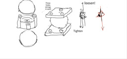
First drawing on left. See there's a ball and two sockets. Just one section of a backbone. You see the holes in the front and the one hole in the back. Strings will go through these vertically all the way up the backbone. Second drawing moving to the right. I show it with just plates to simplify for the next two drawing, but it's the exact same thing as the first. The third drawing I show pulling on the front two strings and loosening the tension on the one in the back. This makes the torso lean to the front or towards you as you look at the picture. You can see the "pitifully" drawn strings and arrows showing them pulling. Now moving to the right you see a half drawn even worse drawing(this is where the "mode" got stuck in some odd ass brush that I could not get it to undo) anyways, this time the string on the front right is pulled down and all the tension is released on the left and half the tension on the back. This makes the backbone articulate towards the right as you are looking at it. I couldn't draw all the strings because..well it screwed up on me so you will just have to imagine them. Basically we have a socket with three directions that can be tensioned so that it can move in any direction, front, back, or either side. Now all you need to operate this is three motors with string tied to pulleys on them that take up slack on the strings by rolling up or unrolling string depending on which way they need to go. The other end of the string is fixed to the top vertebra and the pulleys are on the bottom in this case in the hip. So the whole torso is three motors. Alright let's extend this to the whole body but neglect fingers and toes. Only hands and feet. So we need three motors for each major limb, head, torso, I get 14 for the whole body so 14 x 3 motors each gives you 42 motors for the whole body. For the hands and feet if you have one thumb or toe and two fingers you could probably manipulate whatever you wanted so that's another 3 x 4 for hands and feet, 12 added so 3 x 12=36 motors. Now this would work fine but look a little retarded as every single motion would be an arch. So the spine would be round when it articulated. I have a bit of a kludge idea how to make it look natural and only use three motors for each finger and each toe. At each joint of the finger have a solenoid that pulls a wedge down on the rope so that it stops. This means you could pull the finger in a little then stop it pulling the top or end of the finger but it would still pull close the hand with the next joint down. Like I said it's a kludge and I don't like it but it is cheap and would work but it only saves you one transistor and we already see that these are super cheap. It's going to be tough to find motors with the power we need without using the dreaded gears. I looked briefly at DC motors on ebay just to get some numbers. I found a $12.00 motor with these specs DC 36V, current 0.20A, speed 9000RPM Now I "think" we can use Watts as a short hand for force. I mean an instantaneous force. Like how much someone could pick up and hold in place. (I may be getting this wrong but I think it's right) The actual force would be in Newtons. It says about watts that "...When an object's velocity is held constant at one meter per second against a constant opposing force of one newton, the rate at which work is done is one watt..." Now here's the problem. This definition above I read as you are accelerating at one meter per second against one Newton of force. Now what we want is not acceleration but the actual force that we can pick up and hold. Not acceleration. Yet when you look up "instantaneous force it says,"Power is given as the rate of doing work. In an electrical circuit, the amount of electrical energy dissipated by the load is known as Electrical Power. In an AC circuit, the instantaneous power is given by the product of an instantaneous voltage across the load and the instantaneous current passing through it. "(that's watts but I don;t know how to translate that straight to force to pick up something.) Here's the problem we're looking for pound-force which is directly related to Newtons at a rate of 1N=0.2248089 pound force and one watt is equal to one N but they give it as accelerating. I think as a rough guide we can use the newton to pond force and just call whatever Newtons needed watts but I'm not at all sure about this. How they can call Watts an instantaneous force yet elsewhere call it not is confusing me and it will have to be resolved. We need to be able to use watts as a reference on how much weight a waifu actuator can move. https://en.wikipedia.org/wiki/Newton_(unit) https://en.wikipedia.org/wiki/Watt and yes I do understand watts are based on force and time but I'm trying to take out the acceleration. I'm not explaining this well. If you go to this site and type in Newtins to directly get an equal force or weight in pound force https://duckduckgo.com/?q=newton&t=ffcm&ia=answer it's clear but then when trying to equal that to watts you can not directly do so. I'm supposed to know this but I don't. Someone please explain how to get a pound force using watts as a reference unit.
I'm looking at torque here https://en.wikipedia.org/wiki/Torque and it says "...Also, the unit newton metre is dimensionally equivalent to the joule, which is the unit of energy. However, in the case of torque, the unit is assigned to a vector, whereas for energy, it is assigned to a scalar. This means that the dimensional equivalence of the newton metre and the joule may be applied in the former, but not in the latter case. .." but one Joule for one second is equivalent to one watt so I think if we plug in a pound force and convert it to Newtons we will get an accurate amount we need rated in Watts. An example 200 pound force equals 889.6443 Newtons so if we were to have a motor that held up 200 lbs. for one second we would need a 889.6443 watt motor. Now if we have the voltage and current for this motor we can predict the force it will lift in pounds. So let's use the same numbers. Let's say we have 24 volts and we want to hold up 200 lbs. 889 watts/24 volts=37.0 amps so we would need a 37.0 amp motor to get enough force at 24V to lift 200 pounds. Is this correct?
>>12406 An articulated chain of ball-and-socket joints with integrated clutch plates is a good idea Anon, thanks! I'll consider that a primary load-bearing element to stand in where a normal human spine would. The linear actuators (probably only 8 needed now) would still circle the perimeter of the mid-torso. Their biomechanical-replacement function would sort of stand in for the the pelvic and back muscles. One of our challenges here as designers and engineers is figuring out how to mimic our human motions with mechanical actuators, and still leave volume in the interior to hold batteries, electronics, cooling mechanisms, etc., etc. The torso is an obvious 'spare' volume design target, and this is simply my attempt to work towards that intermediate goal. And BTW 'dime thin' was referring to the outer diameters of both as being similar. I apologize the for the confusing terminology on my part. >>12400 >Helical or heringbone gear to a linear rail? Whichever turns out to have the best compromise of energy/weight/speed/strength/volume/noise aspects. I'm not smart enough to just guess correctly. Only testing would really point us in the right direction. My instinct is that the ball-bearing ones will offer better strength/energy aspects though. Possibly other types ofc. The basic point of my post >"Can you think of an actuator design that works on the principles you are promoting, rather than the more mundane (and slower/noisier) screw-type design?" was to inquire if Anon could think of a non-traditional linear actuator, rather than the ones you suggested.
>>12409 >Is this correct? Even if your ratio analysis and math numbers are correct Anon, seems to me that there's the basic point of mechanical design to consider. Much like Anon's clutch-plates mechanism (>>12406), braking mechanisms such as disc brakes, clutch plates, locking pins, etc., can be utilized to transfer force from the hands alone (which seems to be case for these calculations), and out into the mechanical skeletal framework itself. A robowaifu's skeleton is much better suited to passively supporting weight at the end of an extremity, rather than just her 'muscles' alone. Make sense? Just ask rock-climbers about this, BTW.
I got locked out because the inpenetrable captcha kept giving me horrible pictures and it said I need an "unblock" or something. Sigh. An articulated chain of ball-and-socket joints with integrated clutch plates I didn't make it clear because I was simplifying but the balls would probably not be round but more squashed. They could also be just made of rubber or silicon just like humans. Hmm...maybe balls in between two large washers with the bulk filled with silicon. The silicon would act as a spring. Otherwise just three ropes pulling you could never tell what joint would curve first. With silicon(a spring) it would press on all of them so they would curve equally. The (terribly drawn)drawing I'm adding shows just the plate in the top left. Then below it shows one corner which has been cut away with the rope in it and schematic draw wedges. To the right is just the hole minus the rope for clarity(if any of my drawings can be called clear :) ). It shows wedges that can be pulled up or down depending on which way you want the joint to jam. I really don't like these wedges but it's what I have right now. Need to think of something better. Another idea. I'm surprised I haven't thought of this before. Now I don't like gears because of the noise and trouble with them but I'm certainly not against transmissions. Now we all know a low torque small motor can have a great deal of pforce if it's geared down and a lot of tiny motors can run real fast meaning we could have a substantial amount of force if we could find a way to gear them down. After drawing the string pull spine joint I realized we could do this with an ancient type of gearing. The Chinese windlass, who I think invented it, or a Differential windlass. What a great thing. You can get massive force with this thing. There's an explanation at this link. Do a little math and you will see it has a great deal of force and since little motors run so fast it would still have enough speed. https://en.wikipedia.org/wiki/Windlass I'll also add in a link probably one of the most ingenious transmissions ever invented. Why this is not used everywhere, I don't know. It's brilliant. I wonder if there is some way we could simplify this to work. Check it out. http://www.rexresearch.com/constran/1constran.htm
I forgot to add about the link http://www.rexresearch.com/constran/1constran.htm the transmission can have it's ratio changed very fast. What advantage that would be would it would be much like a human arm in that it could move quickly with little force against it but as force is needed it could slow down and push harder.
>>12471 I think some variant of windlass could indeed be very useful for being able to lift heavy weight relative to robowaifu's. Carrying a full-grown man, for instance. I've actually used block-and-tackle gear on a farm before to pull engines, and it really does work. The engineering trade off comes with the slow rate of progress. It's a pretty common characteristic of basically all fundamental machines (levers, screws, wheels, incline planes, etc) -- higher force faster rate, lower force slower rate. As you've already pointed out more than once ITT, it's power efficiency that will matter most in the end. We have to carry our power packs around with us on our robowaifus, and we'll need to use the system that delivers the most Newtons force for the least Watts electricity. I'm still quite interested in the high-current solenoids using magnetism for linear actuation directly. Any intervening mechanical systems are inevitably going to result in friction waste, and are likely to burn through our available power budgets more quickly.
>>12478 lel. i screwed up the formatting, but I'll assume the message came across regarding the force/rate relationships.
>>12478 "...I'm still quite interested in the high-current solenoids using magnetism for linear actuation directly. Any intervening mechanical systems are inevitably going to result in friction waste, and are likely to burn through our available power budgets more quickly..." Yes. Very much so. I'm extremely enamored of switched reluctance motors. It seems to me the low cost of micro-controllers and MOSFET's has made them the lowest cost, most powerful and most versatile motors around. These can be made with some hunks of iron and a few coils with no expensive magnets needed. The idea I had about using a line and reeling it in around a motor could possibly be used as an actuator which would readily fit the action of a normal muscle. I don't think reeling a line around a pulley on the motor would take up much in the way of friction at all if any worth counting. https://www.controleng.com/articles/resurgence-for-sr-motors-drives/ One thing good about these motors is we can get super high speeds and trade some of this speed for more force if we are reeling in lines as muscles.
Open file (72.62 KB 1912x962 E9M07fjWEAYJ1uS.jpeg)
Open file (75.39 KB 1912x962 E9M07r8WYAQ-xJS.jpeg)
Open file (84.77 KB 1912x962 E9M075iWUAggmVg.jpeg)
>>12389 Elon announced today they're going to use electromechanical actuators on their Tesla bot. https://youtu.be/j0z4FweCy4M?t=7628
>>12496 >related crosspost (>>12492)
>>12482 >I don't think reeling a line around a pulley on the motor would take up much in the way of friction at all if any worth counting. Certainly the ball-bearing based fishing line takeups on good fishing reels seems rather low friction, so yea.
Open file (151.64 KB 643x1024 site.jpg)
Checkout twisted string actuators. They're incredibly light, efficient, and cheap for the large force and stroke they can provide.
>>12683 Thank, already have them on my radar. You probably mentioned them before? But I wonder about how long they would last and how precise they are. These are the other factors to take into account. Then there is this channel here, which seems to have some content on wisted and coiled polymer and other stuff like that: https://youtu.be/IYChiT1CcNc Also related: https://link.springer.com/article/10.1007/s41315-017-0022-x
>>12683 It is an idea that seems to be reasonably light + efficient. There are two issues with it as is, that would need to be solved, AFAICT. 1. Super-coiling. Maybe some kind of narrow guide tube or something to constrain the effect? Not only does super-coiling mess with the smoothness of the motion, it also greatly increases the likelihood of a tangling-up. It also tends to send the line-of-force off in an undesired direction. 2. Gravity/Inertia. Again, maybe the self-same guide tubes? Unlike the cherry-picked, purely-vertical lab example pictured, inside our robowaifus the twisted-string actuator mechanisms will need to function well at literally every possible angle inside them, and under (potentially) widely-varying overall system dynamics (including lifting loads, running, jumping, raucous fugging, etc.)
>>12683 twisted string actuators Yes those look excellent. A built in transmission for force amplification. I just had an idea. What if you used two motors. Say you had two strings just like you showed with the twisted string actuators. One motor would wind up both strings at the same time(no force amplification). The other though would twist. So you could have rapid movement of the limb or whatever then when it needed power it could activate the twist motor and have more force.
>>12737 Neat. That sounds like an innovative approach to dual-force actuator systems anon.
Open file (99.18 KB 525x714 f.png)
>>12685 >Longevity I'll need to build a test jig to figure that out. Thanks, I didn't even consider that. >Precision This can be compensated for with PID control. >>12689 >Super-coiling As long as the servomechanism doesn't require a contraction into the that range, it's no problem. I'll design around it. >Gravity There will need to be an agonist and antagonist pair, just like with human muscles. I'll try coupling the motor to two twisted tring actuators that oppose each other. Also, thanks for mentioning the possibility of entanglement. I'll need to ensure they enclosed. >>12737 So, one side is a winch and the other is a twisted string actuator? That could provide similar functionality to humans compliment of fast-twitch muscles and strong skeletal muscles. Though an exceedingly clever idea, is there anyway to prevent the twisted string actuator from pulling string off the winch?
These twisted string actuators can be super strong. I like to look at stuff like that. Ancioent ways they moved heavy stuff etc. I saw a video where this guy lifted a heavy log like this once. He built a A-frame type tripod(or quadra-pod t-pee type frame, can't remember) over a log then used a wire which he twisted with a stick stuck through it. It was a lot of weight and he lifted it just with this simple stuff by hand.
"... is there anyway to prevent the twisted string actuator from pulling string off the winch..." Maybe I don't understand what you are asking because my first answer is...a knot.
Oh I think I got it. If it twist it would walk off a pulley. Duh sorry I didn't see that. Well if you ran the strings through a couple of holes "before" they went around the pulley that would do it. Twist on the other side of the holes before it goes to the pulley. I still think that if you could come up with a way to 3D print a simplified version of this link http://www.rexresearch.com/constran/1constran.htm that I referenced here >>12471 you would have it licked. Period. Done. The problem is this thing is hard to get your head around. I understand how I could make one of these but simplifying it would be exceedingly hard and take some serious thought. This thing is the perfect transmission which is self regulating, light and can go very fast or very slow with great power. The guy who came up with this, George Constantinesco, was a serious genius. General Motors of course ripped this guy off. They took an option to use it in their cars then...did nothing., Of course he was expecting them to use it in all their cars so he took on debt to do further research and build factories, etc. and when they never paid him any royalties he went bust. They set the contract up so that they paid him one large sum and royalties "when" they used his patent but they also tagged onto that he couldn't sell to anyone else. He being a normal person couldn't understand GM was setting him up to fail from the beginning. I mean if you have the perfect transmission...why not use it? Maybe they were going to wait until he went bust then buy him out for pennies, standard big corp. tactic, and instead he just refused, told them to go to hell and went bust. Ruined him financially. He never really really recovered from that.
Open file (194.14 KB 751x1018 Constantinesco_Car.jpg)
>>12744 >George Constantinesco Sad story, but thanks. His torque converter might b useful for robowaifus. I will look into it a some point.
>>12744 Seems like s rotary to linear converter that uses pendulums and flywheels to smooth out motion and uses a ratchet to convert the linear motion to rotary. A variation uses clutches instead of linear motion into a ratchet. Either way, the fundamental problem is that flywheels and pendulums are wonderful for continuous motion like an engine in a car but, they reduce efficiency and increase latency in systems which rely on non constant one way rotary motion. Also, ratchets and clutches are inherently inefficient. If you can come up with a version that solves the latency and efficiency issues, please do. We need more options. I'm on the twister string/Spanish windlass because it's the simplest and lightest mechanism to move mai waifu at around 90 percent efficiency. I do hope you can develop that mechanism into solving even better, it'd help us all.
>>12748 My aim was for the shoulder movement. I have no specific plan or idea yet, but cutting down on the numbers of motor would be good. So I'd like a mechanism that allows for one motor to rotate while different body parts move only if they connect to the motor.
>>12748 "...Also, ratchets and clutches are inherently inefficient..." I don't think there is any latency at all. If I remeber correctly the gas petal in the car determines where the rod grasp the pendulum./ So if first pushed hard it will go to a low ratio and the motor will rev and give you max torque. I think the motor rev it attached somehow also so as the motor revs to top speed it gradually increases it to higher and higher gears ratios. I would agree clutches are inefficient but I don't agree about ratchets. Especially a particular kind called a Sprag. These things are like magic. https://en.wikipedia.org/wiki/Sprag_clutch Look up some videos of them working they are very cool and will take enormous amounts of power for their size. I saw a sprag for a helicopter, a big one, and it had this little ten inch or so in diameter sprag. I couldn't believe all the power went through it but it does. Very special metal I expect though. Anyways this Constantinesco transmission can use sprags with very little friction. I also don't believe that you need the flywheel. The flywheel is to smooth out the action in a car, I think. I expect you could directly hook it up to the pendulum. I could be very wrong about this these things are simple yet complex at the same time. Another thing is there's no reason you only have to have two connections to the crank and the pendulum. You could use three like a three phase motor. Now here's a off idea. Let's say the rods between the crank and the pendulum are chains or strings because they all work in tension(very important for weight) and you have one motor but two tension members transmitting power. Well when on is going one way the other is going the other way with a clutch to grab them you could operate many different "muscles" with these two sets of rods, strings, chains, whatever going back and forth. You could even have different ratio pendulums on each muscle. Of course the downfall is that you couldn't tailor the movement of each muscle. They could go either way but the force would be fixed to slow big force or fast little force. Constantinesco has a book on this with almost super human mind numbing detail on these things and there's also an biography of him. The tech book is hard to read. Very tech. I can't say I even remotely got all the details. I d understand the basic principles though. He's an old school engineer. Very deep. The biography is great.
>>12751 Using that mechanism to meet the various torque and speed needs of various mechanisms using one actuator with another actuator choosing the output can makeup for the lowered efficiency through mass savings. This is a really good example for a selective output mechanical multiplexer. https://youtu.be/8DWK3zm9SMs
If you really want to get some better idea of what I'm talking about look at this set of articles from the excellent "Low Tech Magazine" https://www.lowtechmagazine.com/2013/01/mechanical-transmission-of-power-stangenkunst.html https://www.lowtechmagazine.com/2013/02/the-mechanical-transmission-of-power-jerker-line-systems.html https://www.lowtechmagazine.com/2013/03/the-mechanical-transmission-of-power-3-wire-ropes.html We always think we are so smart and modern but look at what these guys did with wood and rope. Inspirational stuff. You also can see where Constantinesco's ideas are an evolution of these sort of mechanisms. It looks so odd because no one has really seen this sort of thing in a long time. Or most people anyways.
>>12797 One advantage of what I just talked about is you could run multiple outputs at the same time off the one motor.
Thread alert Thread alert OP, if you're still with us, here's a daily reminder that your most excellent thread is approaching the autosage bump limit for the board (350) and we're less than 15 posts away. It's traditional to link back to the OP of the original thread (this thread) during the OP of a new continuation thread. May #2 be even better!
>>12797 that's pretty effin cool anon thx
>>12796 As a fellow fan of sprag clutches, I'm becoming increasingly curious about a printable design of this mechanism. You clearly understand it better than I do. If you draw a plan, I'll print it to test. >>12798 This magazine is treasure trove of knowledge, mechanical power transmission is very practical.
>Soft muscles with origami-inspired skeletons: https://youtu.be/OJO4FP0DXgQ >Cavatappi artificial muscles: https://youtu.be/yXAJGH5s4cs https://youtu.be/MpCFumHFZvU https://www.designnews.com/automation/cavatappi-robot-muscles-have-5-times-strength-human-muscles >Nameless nanofiber muscle, probably Cavatappi: https://youtu.be/H19p43NFqp4 >Supercoiled polymer (SPC) muscles: https://youtu.be/QHiTJ_zgGME https://youtu.be/N4VMoYFrusg https://youtu.be/hFuzQ4ed-t0 https://youtu.be/2GXWIozM4oQ (bundled/braided) >TCP (the same?) https://youtu.be/S4-3_DnKE9E https://youtu.be/wltLEzQnznM >Twisted string actuators (TSA) I had the idea that they should in some cases be build with a loop. Grippers would hold a part of it and twist that. For fast release they coul let it go and grab the next part of the loop. Designing the gripper will be a bit of a challenge, though. But I think this is doable. Can't image I'm the first having that idea. Not sure if this here >>12589 is already something like it bc I didn't understand it. Here's some passive returning mechanism, followed by other videos on TSAs: https://youtu.be/J26y1nn7JMM https://youtu.be/QBQMZsSQJQM (freaking loud) Effect of bending: https://youtu.be/zYrHGMiqC9A Life cycle test setup: https://youtu.be/PABVsuV7Y1M Frequency response ( I don't get it): https://youtu.be/YLWsh1P80Dc Mixed with fluid/gel tube: https://youtu.be/tP9B3aqc4CI Transmission ratio and speed switch: https://youtu.be/Y1uceDzhjKY https://youtu.be/5PtXTI1t3Po I don't like it being used for fingers but it's a good technology. >Nylon fishing line muscles: https://youtu.be/Za0VeU9Ov7A https://youtu.be/2OuRX65xbKE (Reminder: The do have a high life span >1M) I plan to rather use water for heating and cooling. Continuous ransmission (CVT) / torque converters https://youtu.be/kVPjhmTThPo https://youtu.be/cd2-vsTzd9E https://youtu.be/c9e2y-5DMNc https://youtu.be/PEq5_b4LWNY >Twisted string series elastic actuator (TsSEA) This strikes me as particular interesting. https://youtu.be/VBXykAIBKtA >Printed pneumatics https://youtu.be/_X0rDW6NQ58 Using sugar as soluble support material for printing silicone muscles: https://youtu.be/L0Z0-y3qpNk >>12797 >Mechanical Multiplexer Okay, thanks, looks promising. Especially if only limited to three outputs. But it's a bit loud and I wanted two outputs linked, not in line. >>12799 >Grommet I could always imagine to have a mechanism moving two outputs. But switching between all three options is another thing. And then holding while mooving the other one still isn't solved.
>>12813 This is an important post Anon, and I'd like to have the listing itself at the least included near the top of the thread #2. Kiwi, if you see this, would you mind if I folded this into your OP of #2? Or, I could add it to my own welcoming post next to yours. What I don't have the facility to do here is insert posts, so we'd need rather to modify an existing one.
Open file (281.55 KB 700x900 TanyaApproval.png)
>>12818 Go for it, these links are perfect for the new waifu actuator thread.
>>12821 Done & our thanks to both of you.
I just wanted to mention the idea that if a robowaifu would walk on a plane then the lower leg only needs to move the same distance all the time. So after lifting the thigh a electro magnet in the knee could provide this standard movement of the lower leg. Any problems with that? I also think about another version of that, where the distance is adjustable. Like moving a magnet further away. But I'm not sure if that's the best way, since it would need to be stonger then. >>12406 I started modeling something like this >>12882. But I'm assuming that some of the lines will go through the ribs, not all around the spine. >>12471 Is this on the picture meant to block the rope from going to far? I think so. I thought about the same problem, but why not using knots? >>12409 Thanks for trying to find a way of calculating what kind of forces we need. I'll try to look into it myself. >>12482 >switched reluctance motors This seems to be a reason to be interested in metal machining, beyond cutting some sheets for reinforcement.
>>>12471 "...Is this on the picture meant to block the rope from going to far?..." No. Totally different. The wedges were an attempt to find a super cheap way to "stop" bending of a joint. Say a whole finger only had one motor that curled up the whole finger "but" it did have joints in the finger like a regular finger. You pull "all" the fingers closed with one motor. A bit of a kludge but it does seriously cut cost by a lot. So as the fingers are being closed you could lock any number of joints and the ones below it still being pulled closed would continue to close. The wedges are a super cheap way to do this driven only by a electro-actuator instead of a motor. The point of this was say you wanted to move a finger at the root like pointing but keep the rest straight. You could lock all finger joints except the root one(one closest to the hand) and it would move the straight finger up and down. Again it's kludge but with some thinking it could look somewhat natural. I repeat this is a kludge solely to cut cost and in no way is ideal. It could cut cost for prototypes also. In the end I can't see any really decent waifu that didn't have all the muscles actuated individually but that would take some 300 motors to have a real life like figure. >switched reluctance motors "This seems to be a reason to be interested in metal machining, beyond cutting some sheets for reinforcement." I just read the other day about people machining rifling in guns with copper wire, a plastic 3D printed die, salt water in a bucket and a normal battery charger. Called electronic Discharge Machining(EDM). So I look at this stuff and some people are doing this at home cheap. The commercial stuff is NOT cheap but you can do this cheap. Here's the significance of this. If you are going to make cheap reluctance motors you are likely going to have to stamp them out with sheets of metal and then glue them together. Much like transformers are stack of metal glued together. The easiest way to do this is to build a punch that smashes them out. The metal needed to do so is super hard to make dies for the punch but if you EDMed them you could do this cheaply. Let's say you are building these reluctance motors you could probably get by with three sizes or maybe even one and then double, triple or whatever number needed to get the force you want. Let's say just one type motor. Then you just need one cutting stamp to cut out the motor and maybe one stamp and die to make a pocket for the bearings. Glue these all together and you have all the metal parts for the motor.
Look at this, Piezoelectric motor https://www.youtube.com/watch?v=uFZsH62ewYo If it just didn't have high voltage, sigh. Super interesting though. What if we could simulate this inch worm effect but do it with sort of magnetic actuator effect??? I'll have to think about this.
>>12912 >Here's the significance of this. If you are going to make cheap reluctance motors you are likely going to have to stamp them out with sheets of metal and then glue them together. Much like transformers are stack of metal glued together. The easiest way to do this is to build a punch that smashes them out. The metal needed to do so is super hard to make dies for the punch but if you EDMed them you could do this cheaply. >Let's say you are building these reluctance motors you could probably get by with three sizes or maybe even one and then double, triple or whatever number needed to get the force you want. Let's say just one type motor. Then you just need one cutting stamp to cut out the motor and maybe one stamp and die to make a pocket for the bearings. Glue these all together and you have all the metal parts for the motor. For men who don't have any familiarity with this, your descriptions are kind of an opaque mystery. This is no fault of yours, I'm just pointing out I can't really picture what you're saying Anon. If you wouldn't mind, could you make some sketches to diagram out things like >Then you just need one cutting stamp to cut out the motor and >and maybe one stamp and die to make a pocket for the bearings ? They say 'a picture is worth a thousand words', and a few might help any uninitiates such as myself get over the hump to understanding your meanings. TIA.
I did use some verebage incorrectly. I should have said you punch out parts then stamp them to add form. Here's a link that explains this. http://austgen.vn/blogs/what-is-metal-stamping
Here's some more. If you look at any type can that has some sort of from on it this is how it's made. They punch out the metal then use a press to form it into shape. https://www.youtube.com/watch?v=FNxLaEZwH-o https://www.youtube.com/watch?v=JmAyep2V-Cw
>>12916 >>12917 That's fine, thank you very much!
I'm confused. We have a new thread for muscles / actuators >>12810 but now the old one seems to be below the bump limit and come up again.
NEW THREAD NEW THREAD NEW THREAD >>12810 >>12810 >>12810 >>12810 >>12810 NEW THREAD NEW THREAD NEW THREAD This thread is autosage, convos should be relocated to the new edition #2.

Report/Delete/Moderation Forms
Delete
Report